Creating a Hub & Spoke network in Azure with Virtual Network Manager
A guide to creating a Hub & Spoke topology in Azure using Azure Virtual Network Manager, Bicep and Azure CLI.
Last updated on
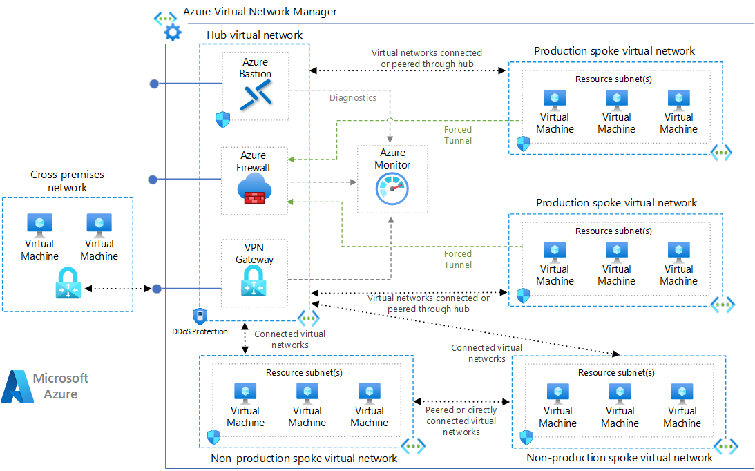
Networking within Azure may seem complex and not very intuitive at a first approach, especially if your background comes from the on-premises world.
Over time, however, a whole series of tools have emerged within the platform that allow you to manage and automate the management of Virtual Networks in a simple and structured way.
Figure 1: Infrastructure design of a Hub & Spoke network in Azure
One of these examples is Azure Virtual Network Manager, which allows you to create network topologies within Microsoft’s cloud platform in multi-subscription and even multi-tenant contexts.
The topology examined in this guide is the Hub & Spoke, made up of a central Hub that contains shared and management resources such as the Firewall, Azure Bastion, the Virtual Network Gateway, etc… and the spokes, which are used to segregate and govern the various workloads hosted on them.
Requirements
To perform the proposed configuration you will need the following:
-
Entra ID tenant
-
Azure Subscription
-
VS Code
-
PowerShell 7 with Bicep and Az-Cli
Creating the virtual networks
To create the Virtual Networks, I recommend using Bicep scripts, which allow you to quickly create all the networks required for the Hub and Spoke topology without the need to use the portal.
Below are the necessary scripts and the PowerShell commands to deploy the resources within Microsoft Azure. At the following LINK I leave my GitHub repository with the code.
Resource Group:
targetScope = 'subscription'
param location string = 'italynorth'
resource rgHub 'Microsoft.Resources/resourceGroups@2021-04-01' = {
name: 'RG-WPC-HUB-ITN-01'
location: location
}
resource rgSpk1 'Microsoft.Resources/resourceGroups@2021-04-01' = {
name: 'RG-WPC-SPK-ITN-01'
location: location
}
resource rgSpk2 'Microsoft.Resources/resourceGroups@2021-04-01' = {
name: 'RG-WPC-SPK-ITN-02'
location: location
}
Virtual Network Hub:
param location string = 'italynorth'
resource vnetHub 'Microsoft.Network/virtualNetworks@2021-02-01' = {
name: 'vnet-prod-hub-itn-01'
location: location
properties: {
addressSpace: {
addressPrefixes: [
'172.16.10.0/24'
]
}
subnets: [
{
name: 'AzureBastionSubnet'
properties: {
addressPrefix: '172.16.10.0/26'
}
}
{
name: 'AzureFirewallSubnet'
properties: {
addressPrefix: '172.16.10.64/26'
}
}
{
name: 'GatewaySubnet'
properties: {
addressPrefix: '172.16.10.128/27'
}
}
]
}
}
Virtual Network Spoke-01:
param location string = 'italynorth'
resource vnetSpk1 'Microsoft.Network/virtualNetworks@2021-02-01' = {
name: 'vnet-prod-spk-itn-01'
location: location
properties: {
addressSpace: {
addressPrefixes: [
'172.16.11.0/24'
]
}
subnets: [
{
name: 'snet-prod-iaas-itn-01'
properties: {
addressPrefix: '172.16.11.0/28'
}
}
]
}
}
Virtual Network Spoke-02:
param location string = 'italynorth'
resource vnetSpk2 'Microsoft.Network/virtualNetworks@2021-02-01' = {
name: 'vnet-prod-spk-itn-02'
location: location
properties: {
addressSpace: {
addressPrefixes: [
'172.16.12.0/24'
]
}
subnets: [
{
name: 'snet-prod-paas-itn-01'
properties: {
addressPrefix: '172.16.12.0/28'
}
}
]
}
}
Once the repository has been cloned, I recommend using the PowerShell terminal in VS Code to move into the folder where you placed the scripts:
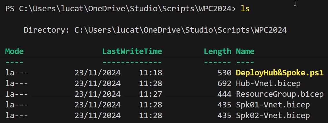
Figure 2: VS Code terminal used to set the path to the folder containing the BICEP scripts
At this point you can use the PowerShell commands below to first log in to your target tenant and then deploy the resources in Azure through the “az deployment” command:
PowerShell in VS Code:
#Login to azure
az login --*insert your Tenant ID*
# Deploy Resource Group
az deployment sub create --location italynorth --template-file .\ResourceGroup.bicep
# Deploy Bicep File to Specific resource Group
az deployment group create --resource-group RG-WPC-HUB-ITN-01  --template-file .\Hub-Vnet.bicep
az deployment group create --resource-group RG-WPC-SPK-ITN-01  --template-file .\Spk01-Vnet.bicep
az deployment group create --resource-group RG-WPC-SPK-ITN-02  --template-file .\Spk02-Vnet.bicep
For the sake of clarity, the steps performed by the script are 3:
-
Login to Azure
-
Creation of the Resource Groups in the Italy North region
-
Creation of the Virtual Networks in the Resource Groups mentioned in the previous point
Once the scripts have been run, you can access the Azure portal to verify the result:
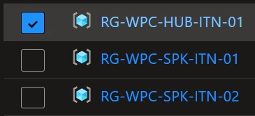
Figure 3: Verifying the creation of the Resource Groups
Let’s now check that the VNets have been deployed with the correct configurations:
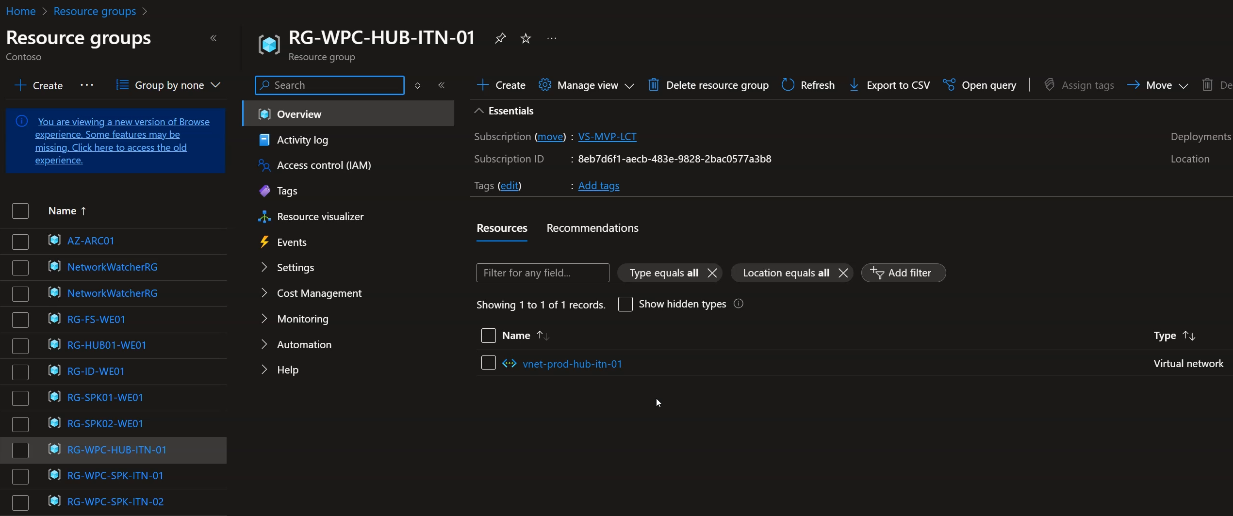
Figure 4: Verifying the creation of the Hub VNET
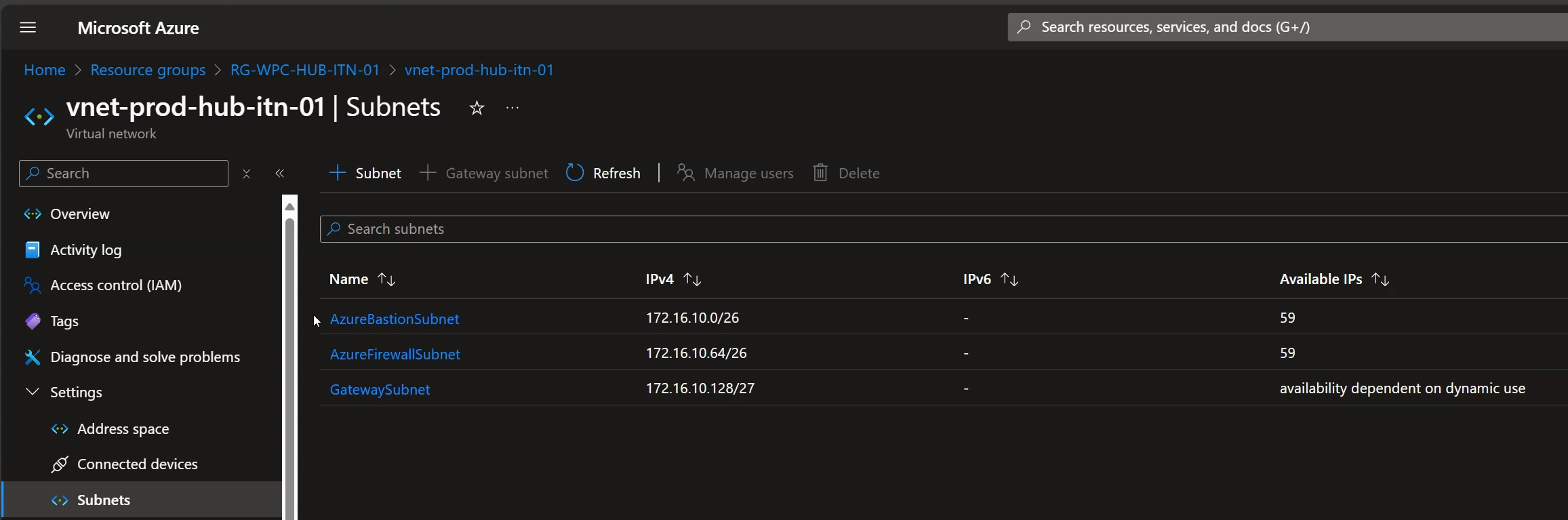
Figure 5: Verifying that the Subnets have been added to the Hub VNET
Implementing Virtual Network Manager
As seen in the previous steps, at this moment we have deployed three different VNets, with their respective Subnets.
Now, however, it is time to create a Hub & Spoke topology through the use of Azure Virtual Network Manager.
The tool will autonomously create the peerings needed for communication or, if they already exist, it will adapt to the existing configuration. This means you can use it right away on already existing configurations that may need additional features such as Security Admin Rules and/or Direct Connectivity.
Once logged in to the Azure portal we can click the search field and type the name of the service “Virtual Network Manager”, then click the correct result:

Figure 6: Searching for the Virtual Network Manager service
Now click “Get Started” and then “Create a network manager”
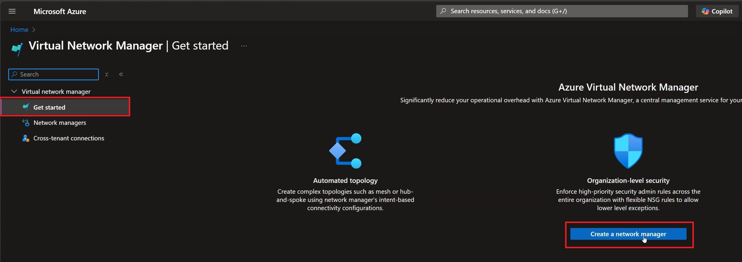
Figure 7: Click “Create a network manager”
Fill in the various fields using the Resource Group dedicated to the HUB network, in this case “RG-WPC-HUB-ITN-01”, choose the name and the region and finally select the “Features” you want to enable, in this case “Connectivity” and “Security admin”:
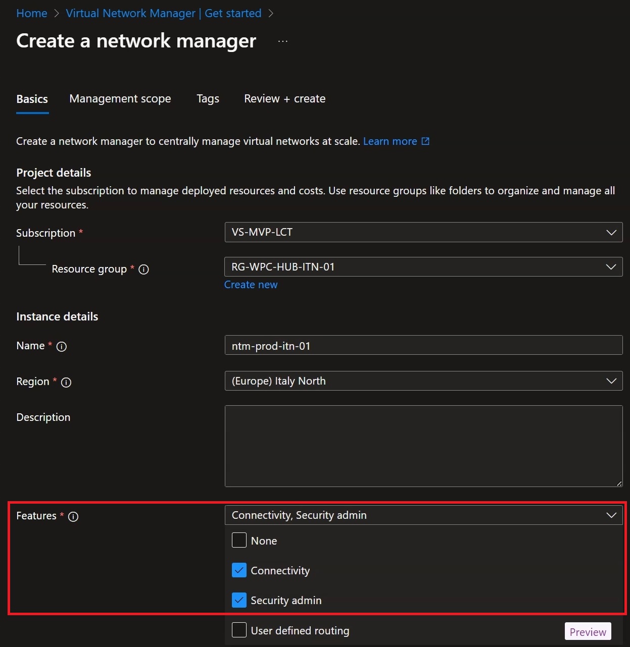
Figure 8: Selecting the features we need
Once all the fields have been filled in, click “Next: Management Scope”:
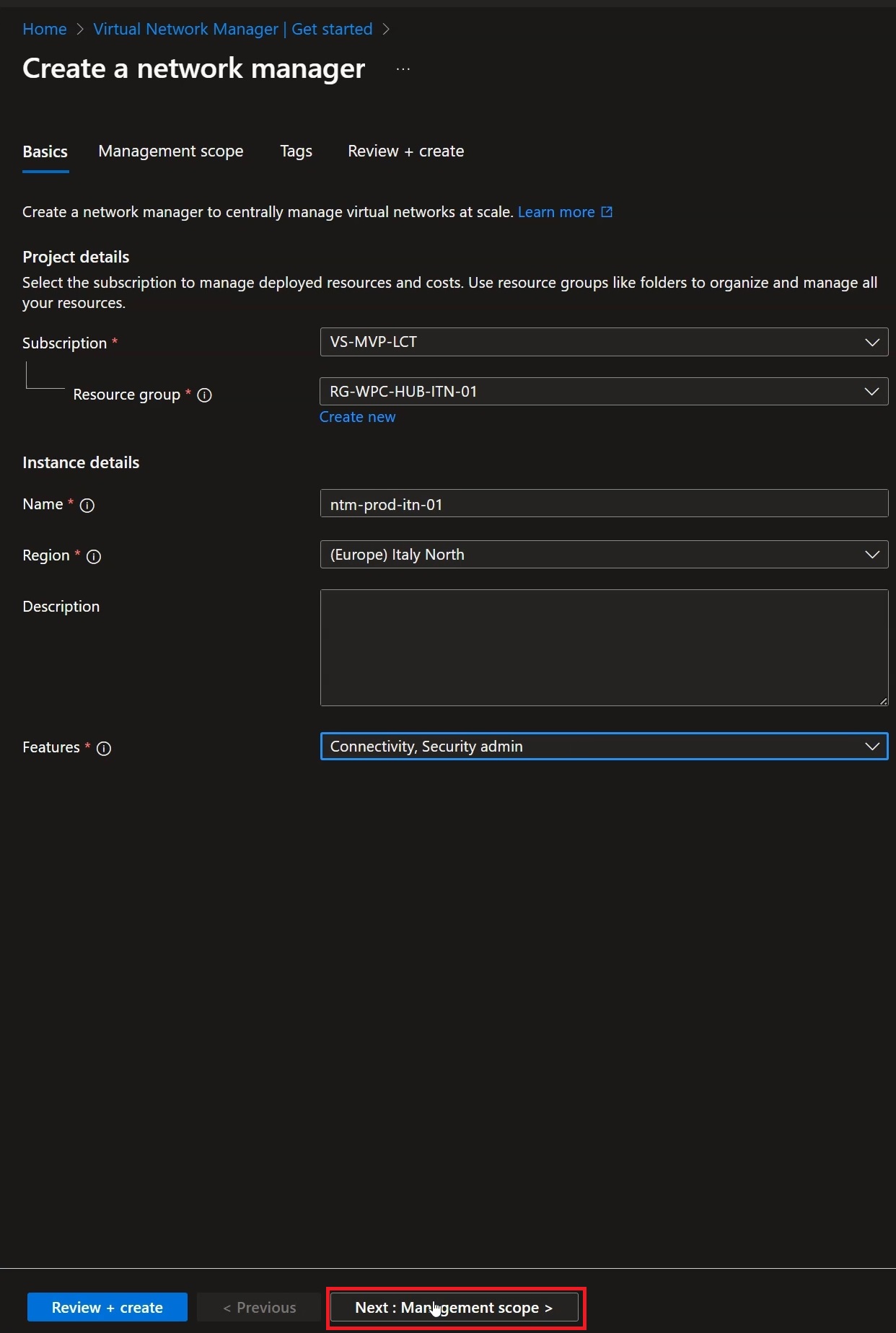
Figure 9: Click “Next: Management scope” to select the Tenant and Subscription to manage
Within this section, select “Add” to add the Subscriptions where your VNets are contained:
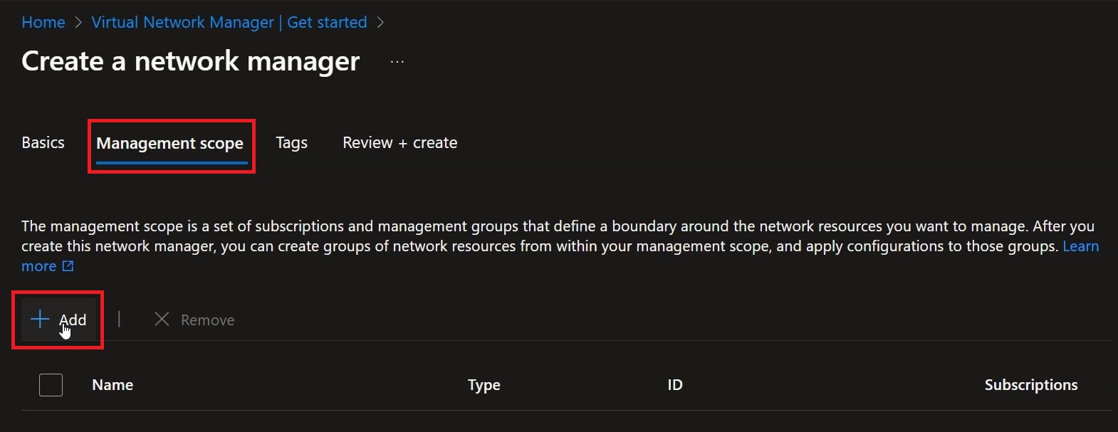
Figure 10: Selecting “Add” to add the correct Subscription
Select the Subscription where your VNets are present, then click “Select”:
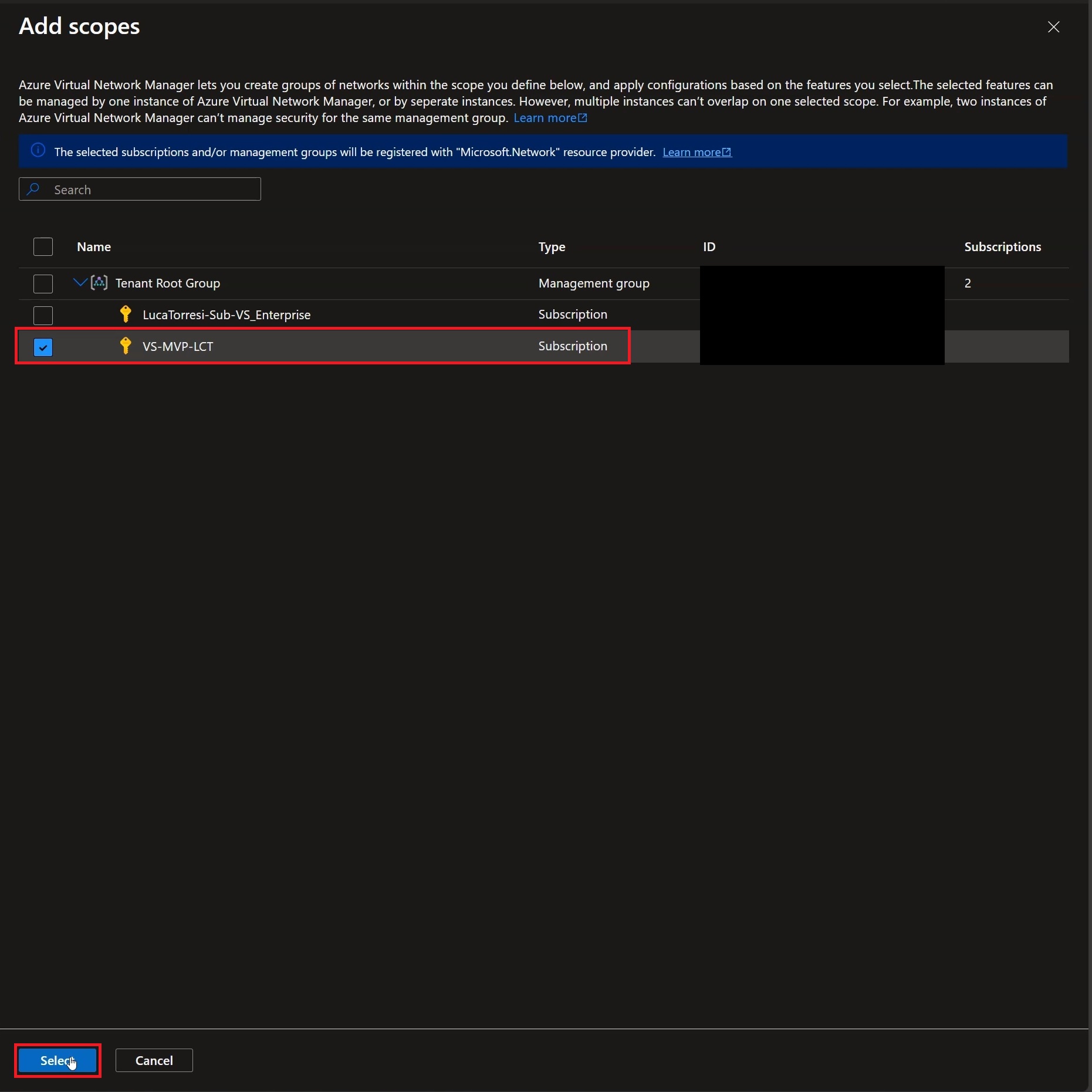
Figure 11: Once the correct Subscription is selected, click “Select”
Verify that the target Subscription has been added correctly, then click “Tags”:
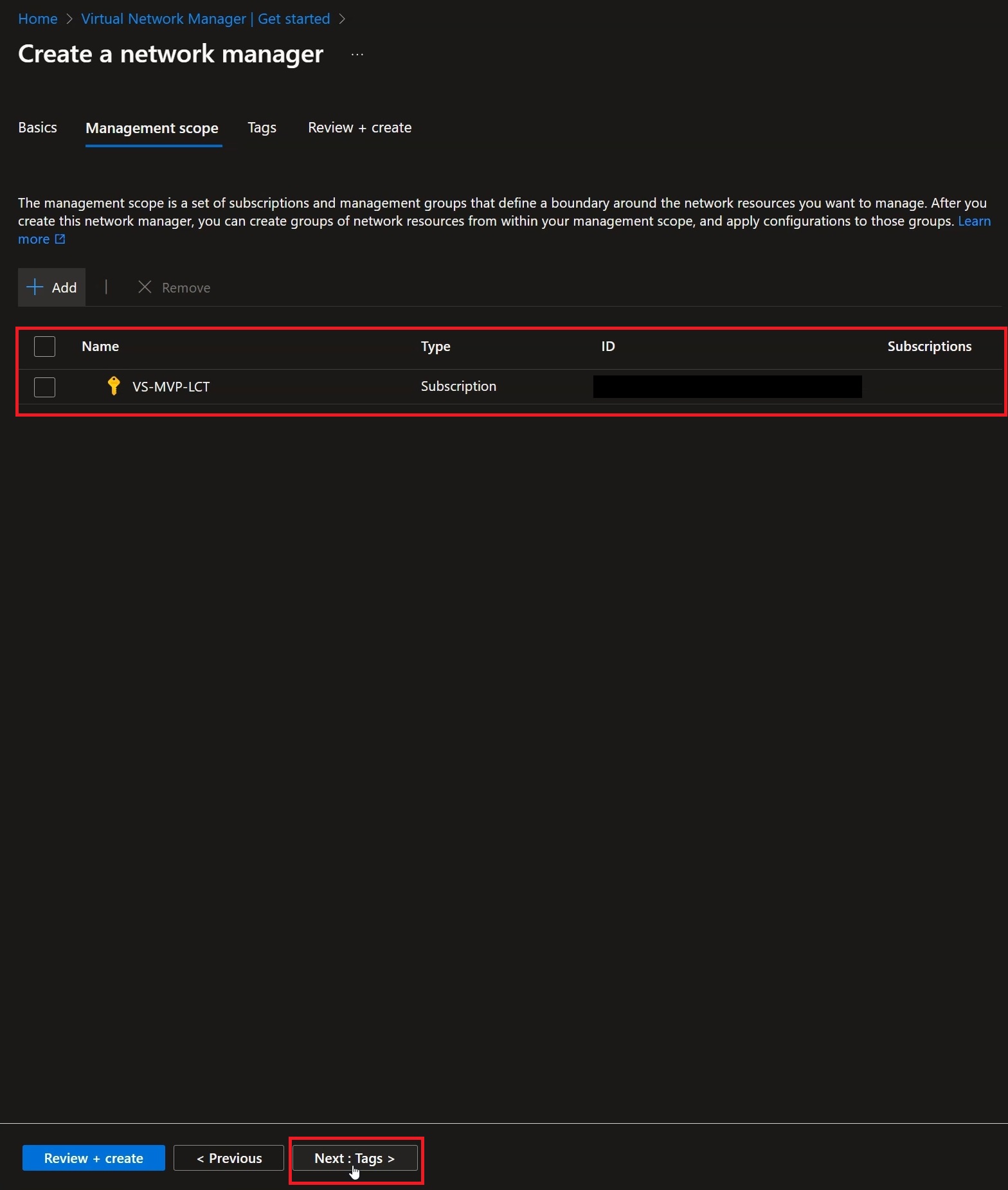
Figure 12: Click “Next” to add the tags
Click “Review + Create”:
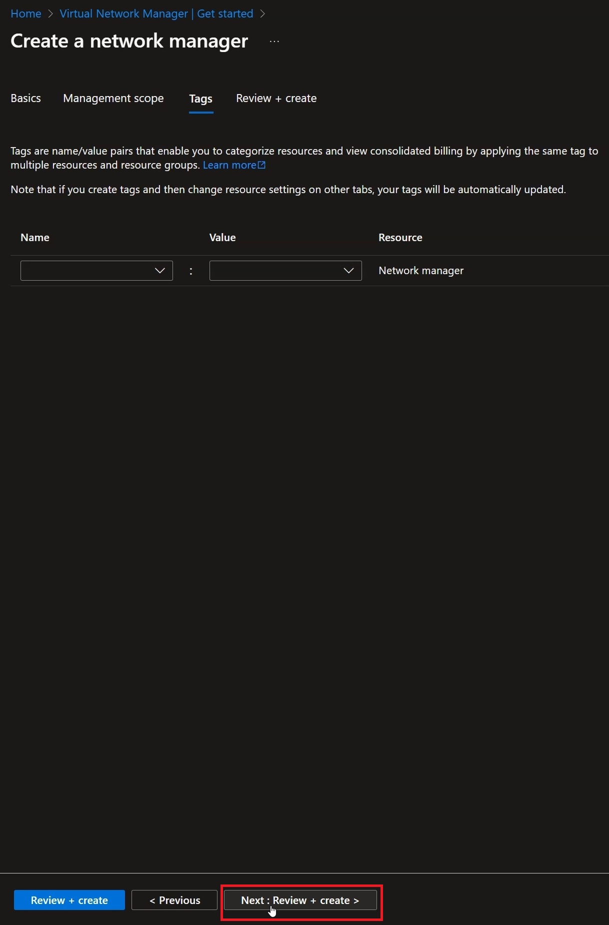
Figure 13: Click “Review + create”
Check that the settings are correct and then click “Create”:
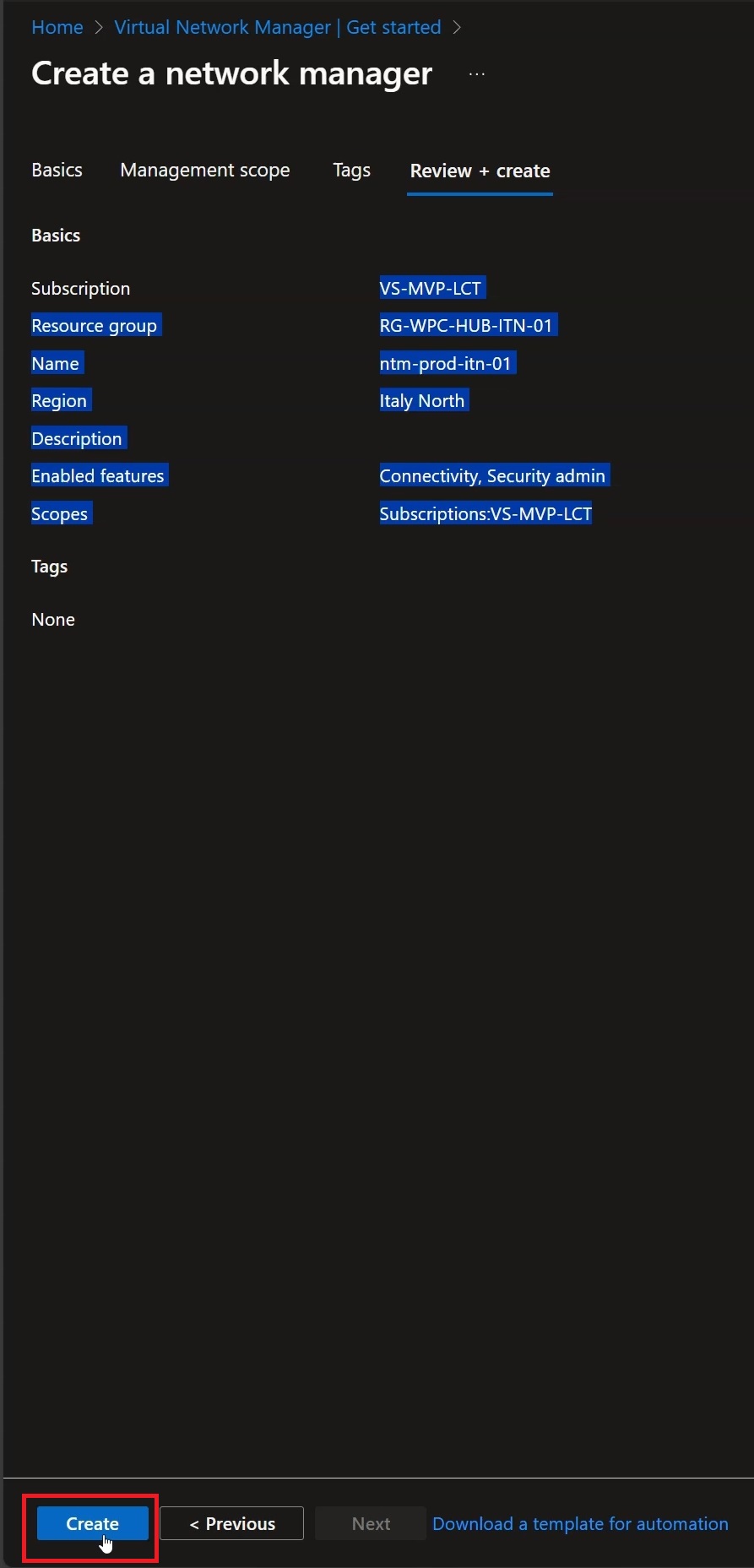
Figure 14: Click “Create” to proceed with the creation of the Azure resource
Once the resource deployment is complete, you can click “Go to resource” to reach the page dedicated to Virtual Network Manager:
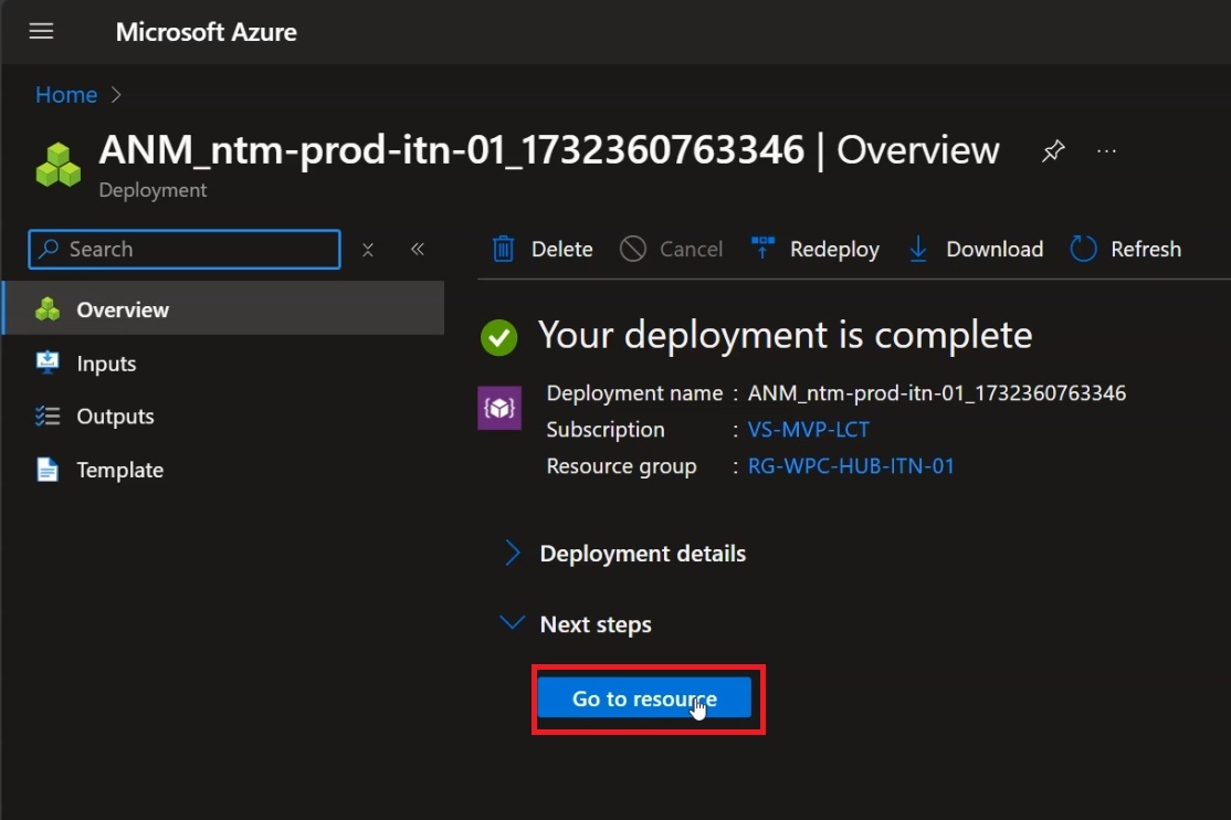
Figure 15: Click “Go to resource” to verify the result
Once at the Virtual Network Manager screen, click “View Network Groups” to start creating the Hub & Spoke network topology:
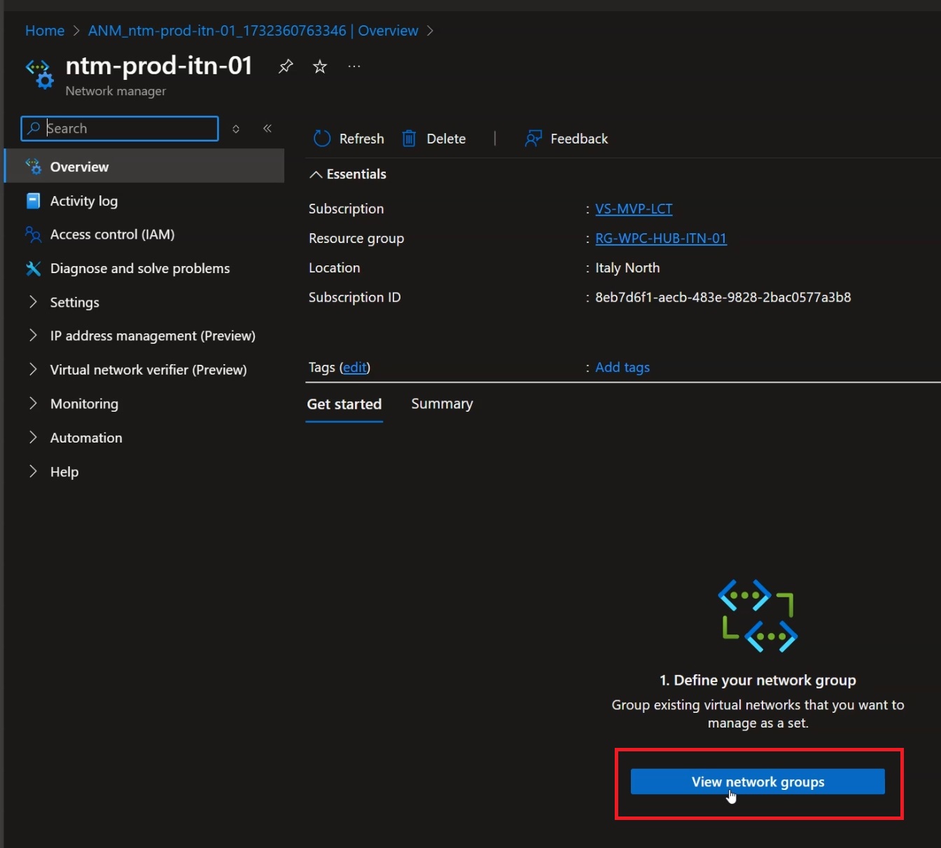
Figure 16: Click “View network Groups” to move on to creating the Network Groups
Click “Create” to start creating the Network Group:
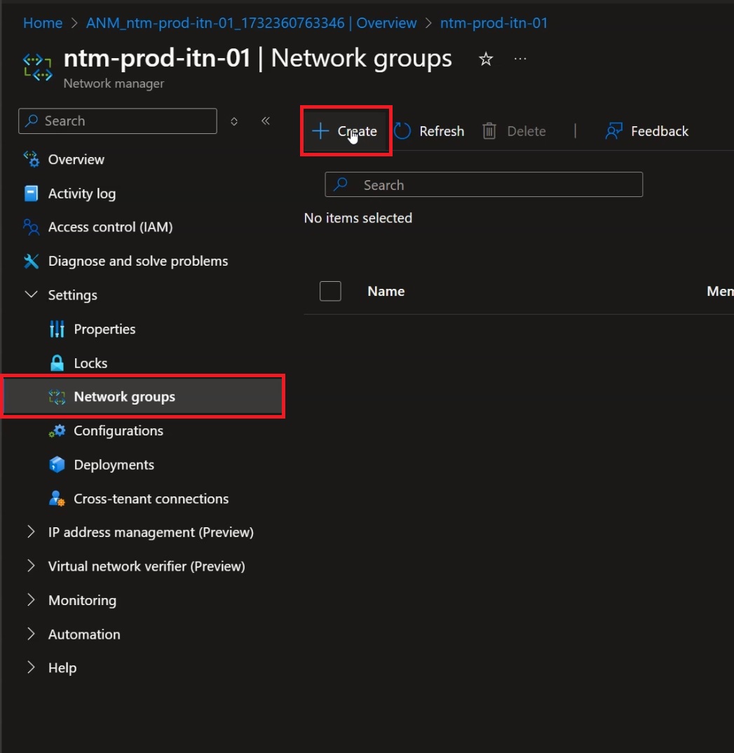
Figure 17: Click “Create” to create the first Network Group
Assign a name and the membership type as shown in “Figure 18”, then click “Create”:
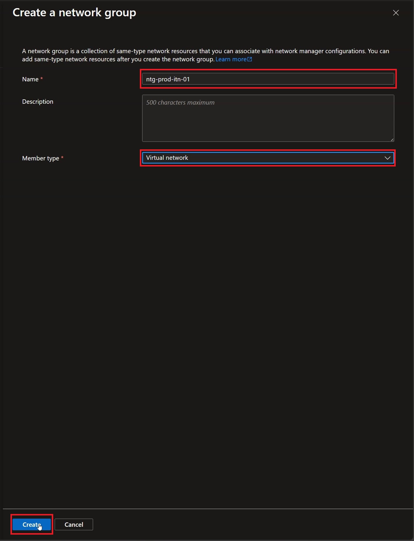
Figure 18: Add a Name and the membership type, then click “Create”
Once the new Network Group has been created, click the object to add the VNets that will be part of it:
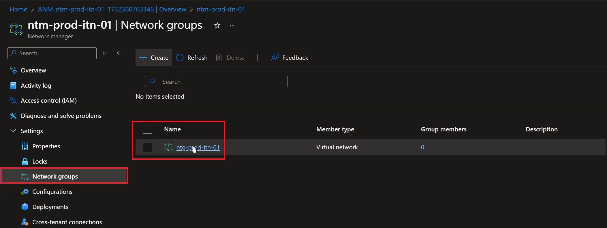
Figure 19: Click the new object to move on to adding the Virtual Networks
Click “Add virtual Networks” to start the procedure of adding the VNets:
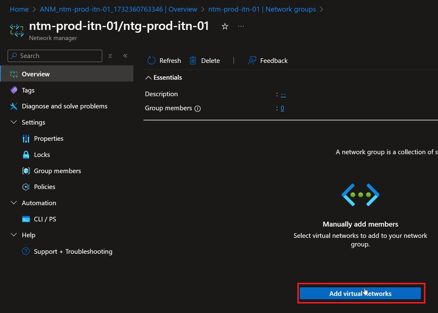
Figure 20: Click “Add virtual networks” to add the VNets
Add only the Spoke VNets, then click “Add”:
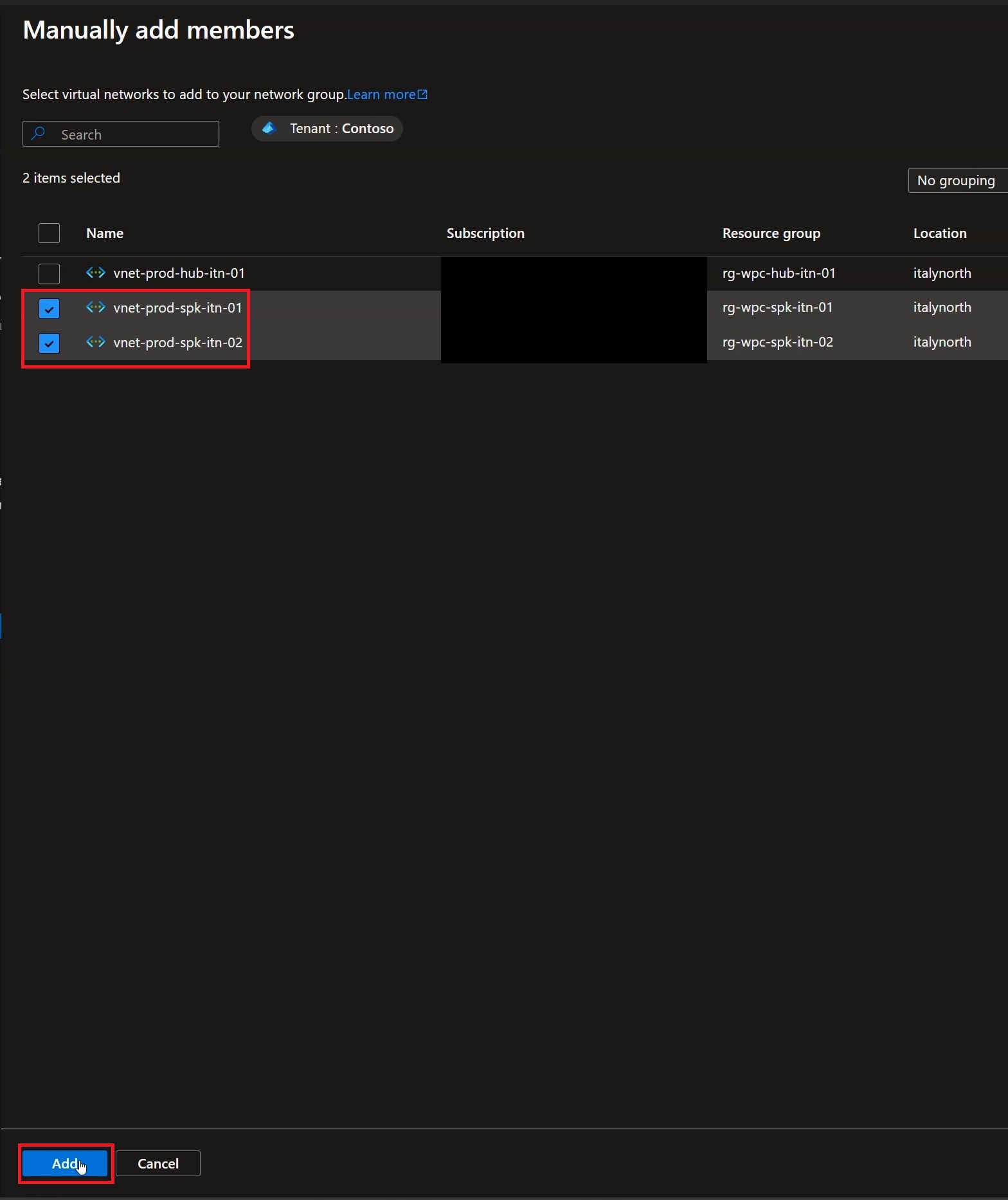
Figure 21: Select only the Spoke VNets and click “Add”
Verify that the number of VNets you added matches what was entered in the previous step:
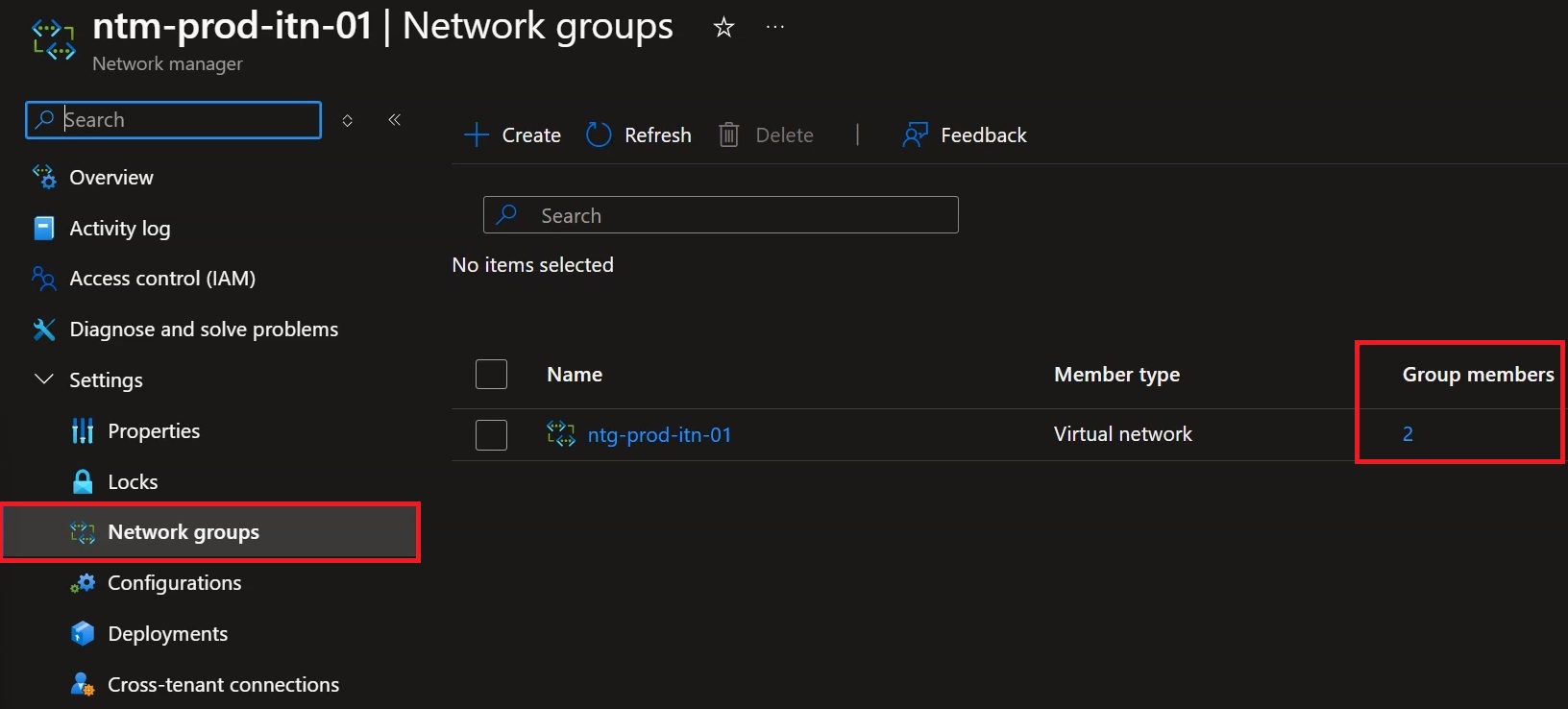
Figure 22: Verify that the number of VNets that are part of the Network Group is consistent with the choices made
At this point click “Configurations” in the left-hand column, then “Create connectivity configuration”:
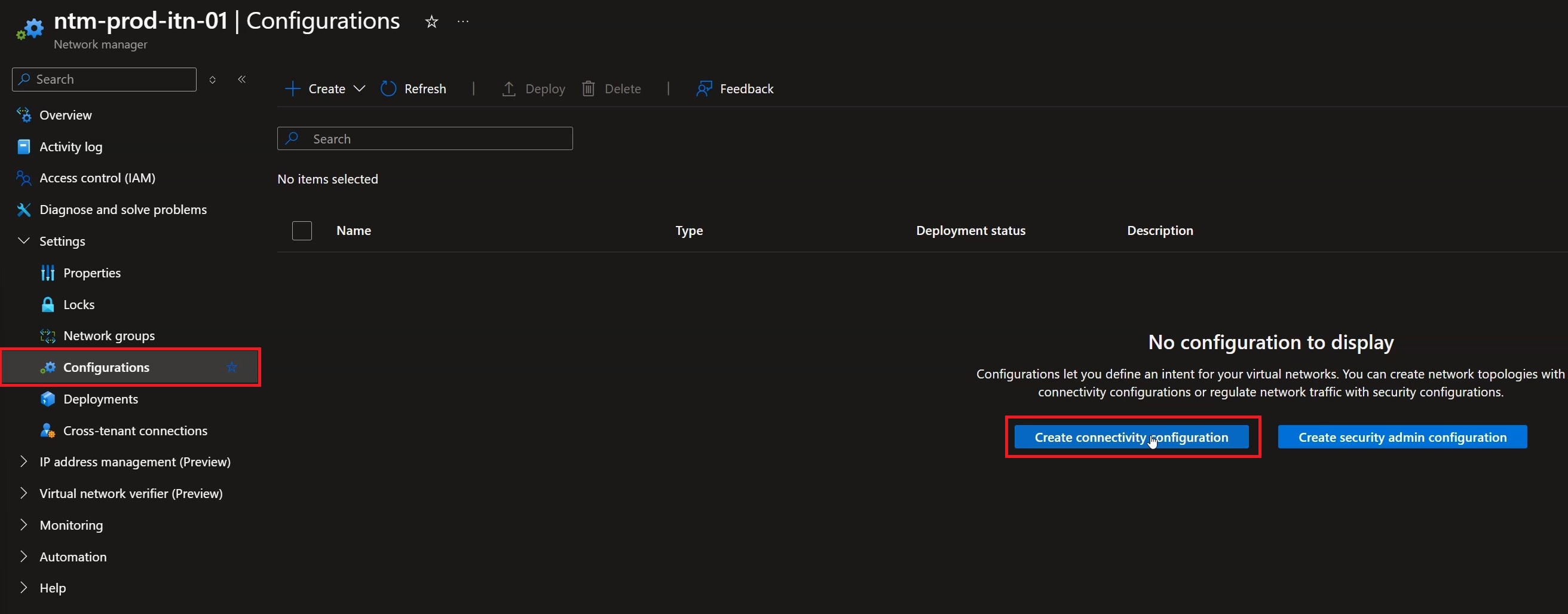
Figure 23: Move to the “Configurations” tab and click “Create Connectivity Configuration”
Fill in the desired name and click “Next: Topology”:
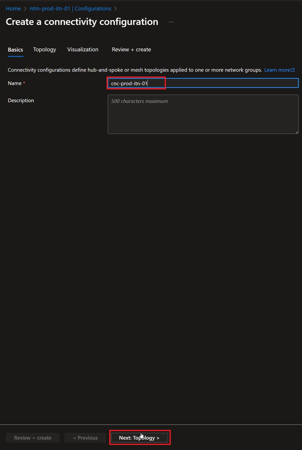
Figure 24: Enter a name and click “Next: Topology”
Within the topology section, select “Hub and spoke” and then “Select a hub”:
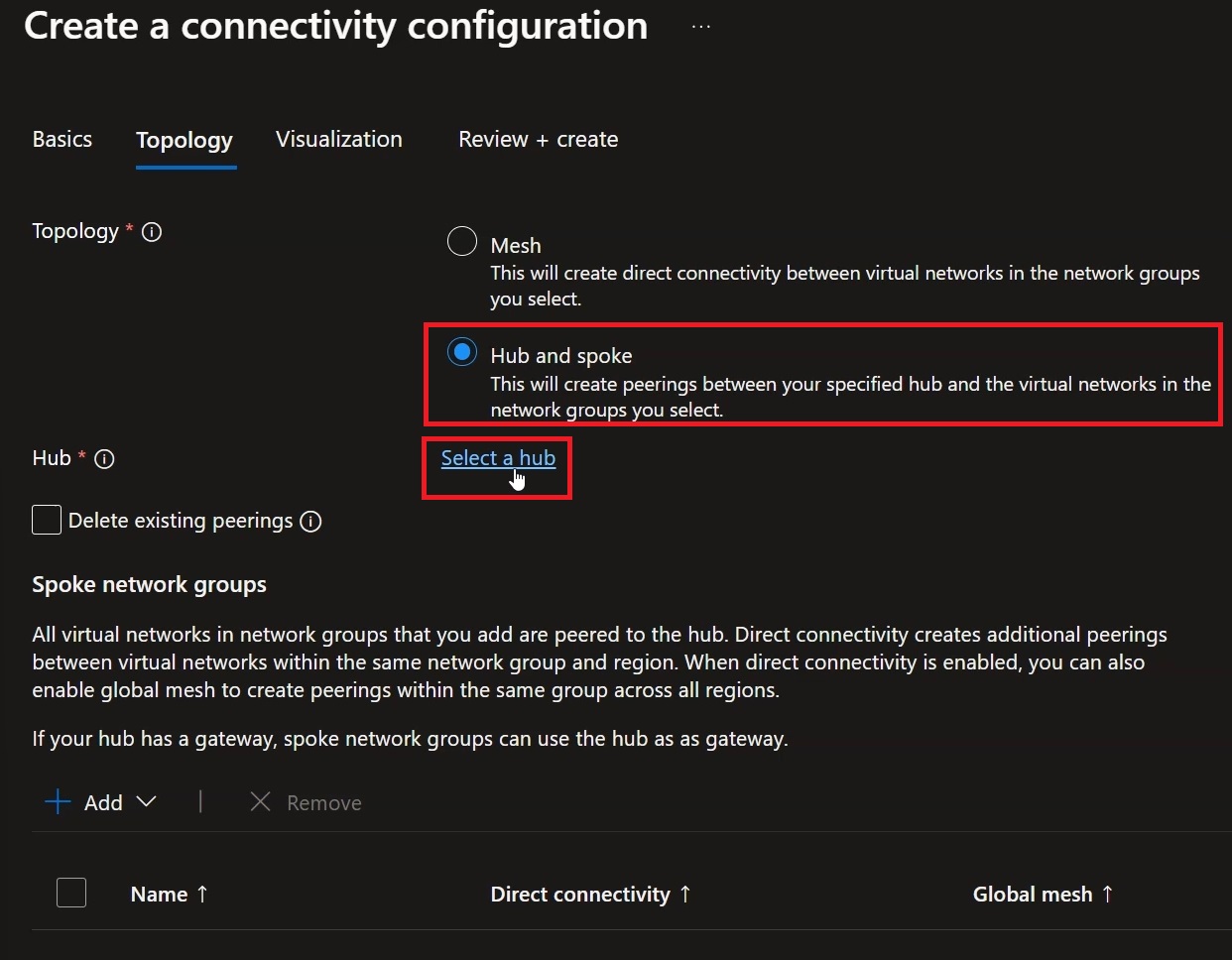
Figure 25: Click “Hub and spoke” and then “Select a Hub”
Select the Hub VNet, then click “Select”:
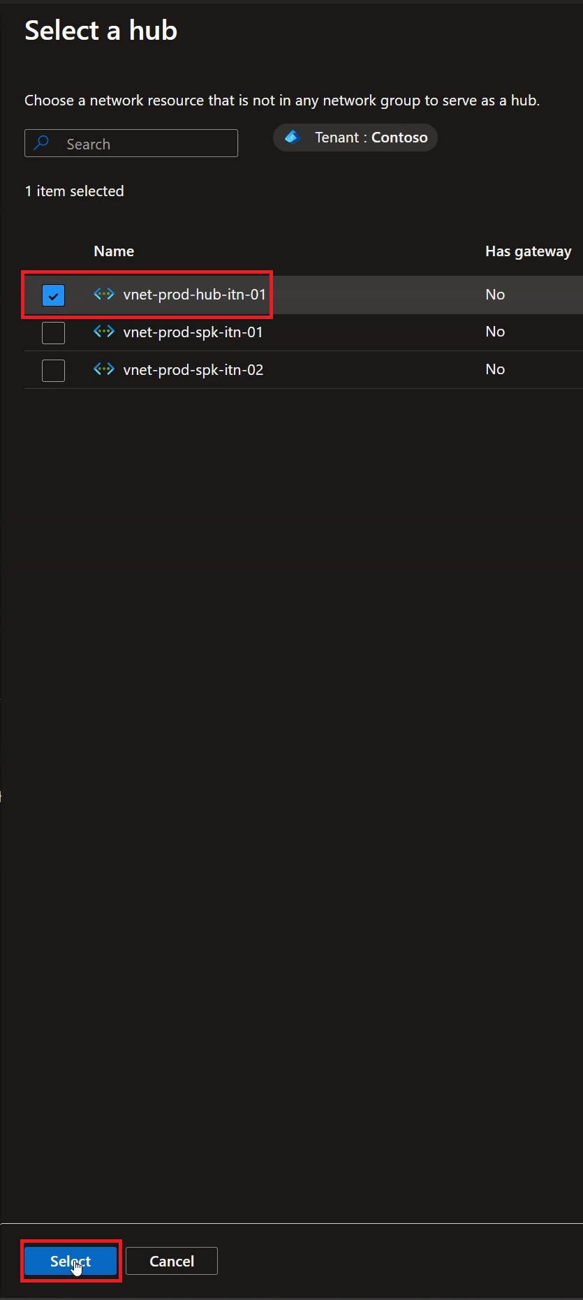
Figure 26: Select the Hub VNet and click “Select”
Moving to the lower section we can click “Add” and “Add network groups”:
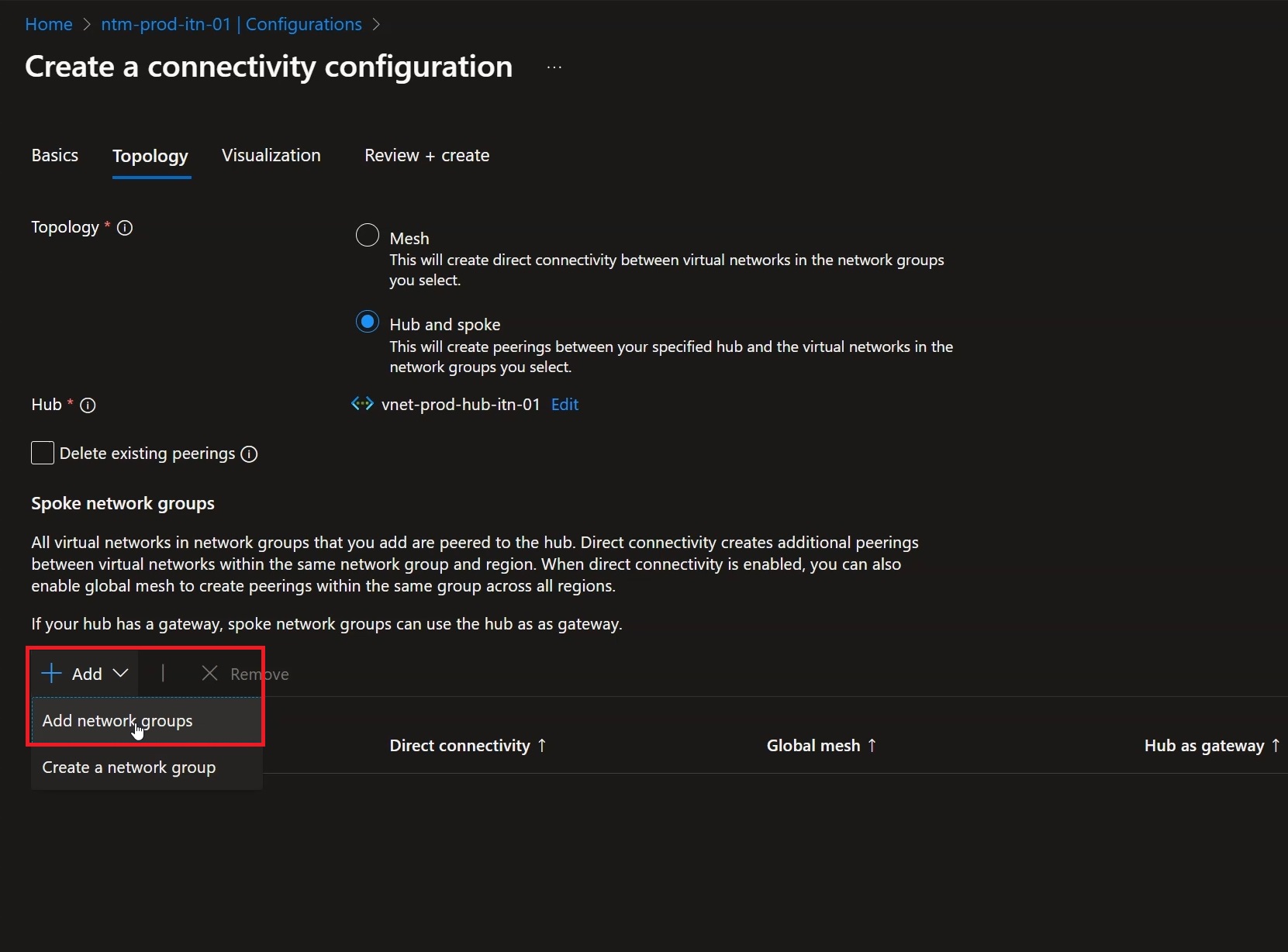
Figure 27: Click “Add” and then “Add network Groups”
Now select the Network Group created earlier and then click “Select”:
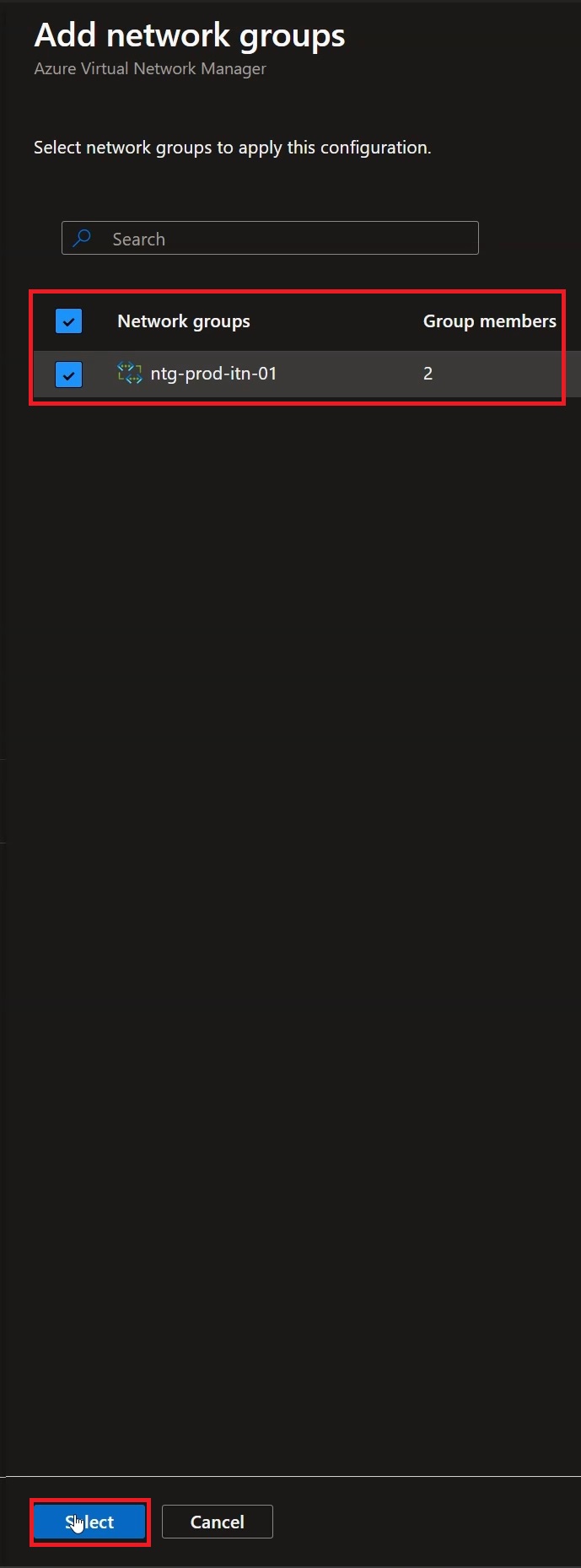
Figure 28: Add the Network group created earlier and click “Select”
Verify the information entered and, once ready, click “Next: Visualization”:
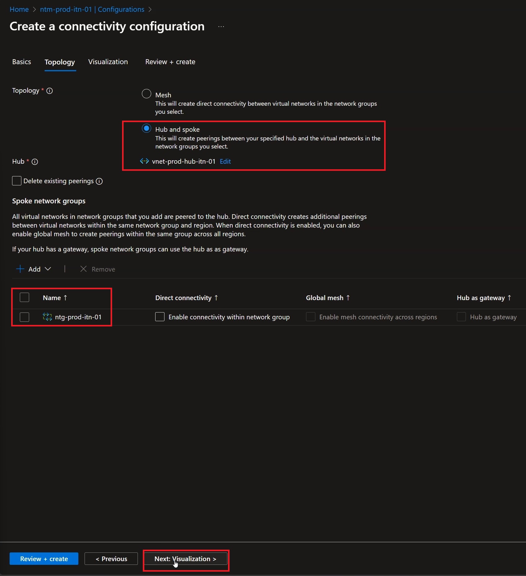
Figure 29: Click “Next: Visualization” to verify the configurations just entered
After reviewing the new topology that will be created, you can click “Next: Review + create” to proceed with the setup:
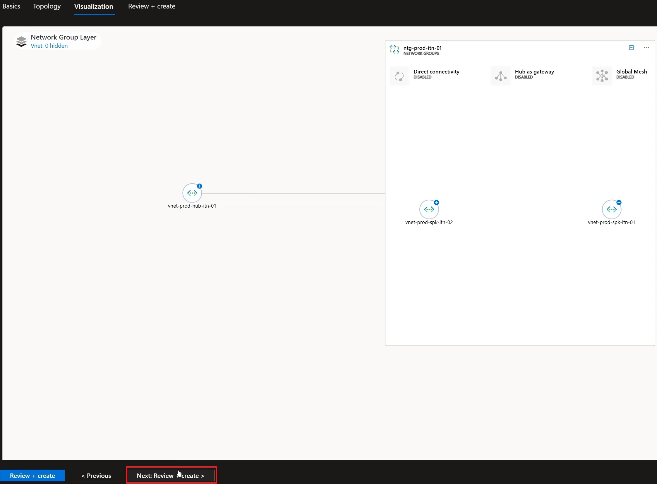
Figure 30: After reviewing the new topology you can click “Review + Create”
Once you have verified all the information you can click “Create”:
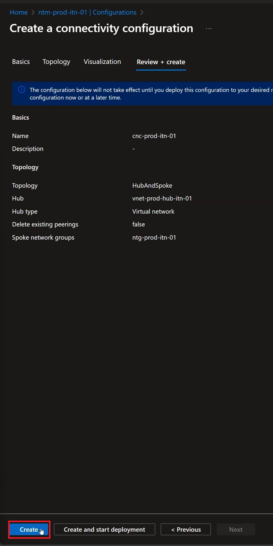
Figure 31: After reviewing the configurations click “Create”
At this point move to the “Configurations” tab to verify the configuration just created:
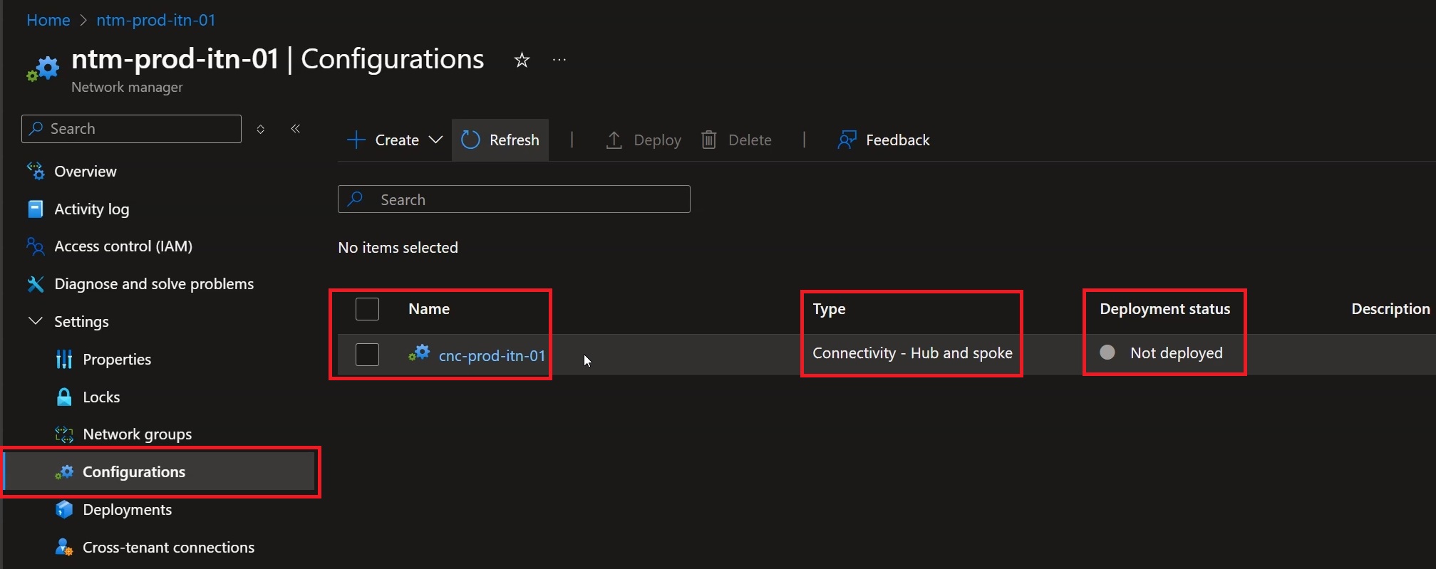
Figure 32: Move to the Configurations tab to verify that the object has been created correctly
Finally, move to “Deployments” for the final phase:
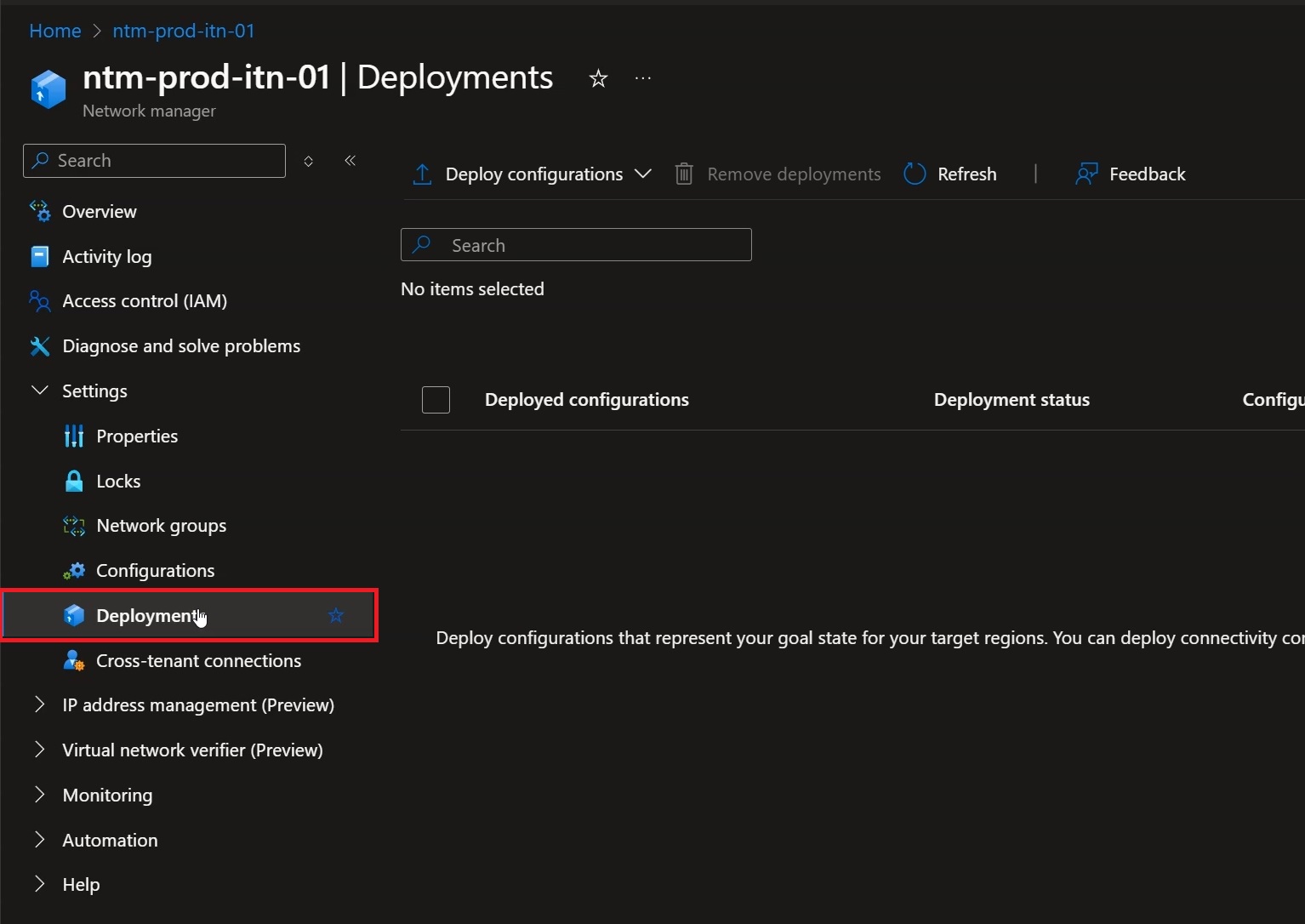
Figure 33: Move to the “Deployment” column
Within the “Deployments” tab click “Deploy Configurations” then “Connectivity Configurations”:
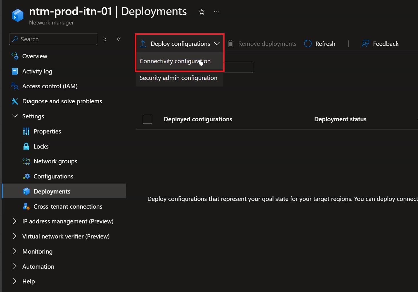
Figure 34: Click “Deploy configurations” and then “Connectivity configuration”
In the “Goal state” section select the correct “Connectivity Configurations” and the target “Region” of your deployment, in this case “Italy North”. When done, click “Next”:
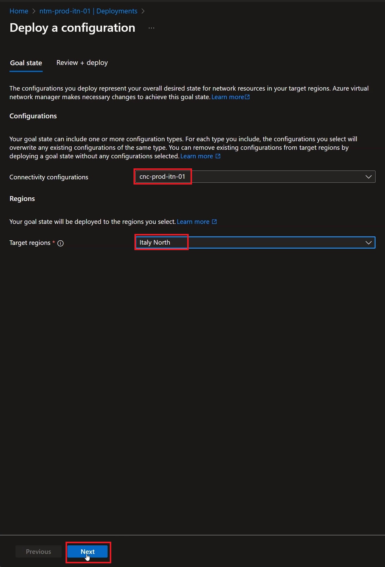
Figure 35: Select the correct configuration and region, then click “Next”
Verify the new configuration, then click “Deploy” to deploy the new configuration, thus completing the setup:
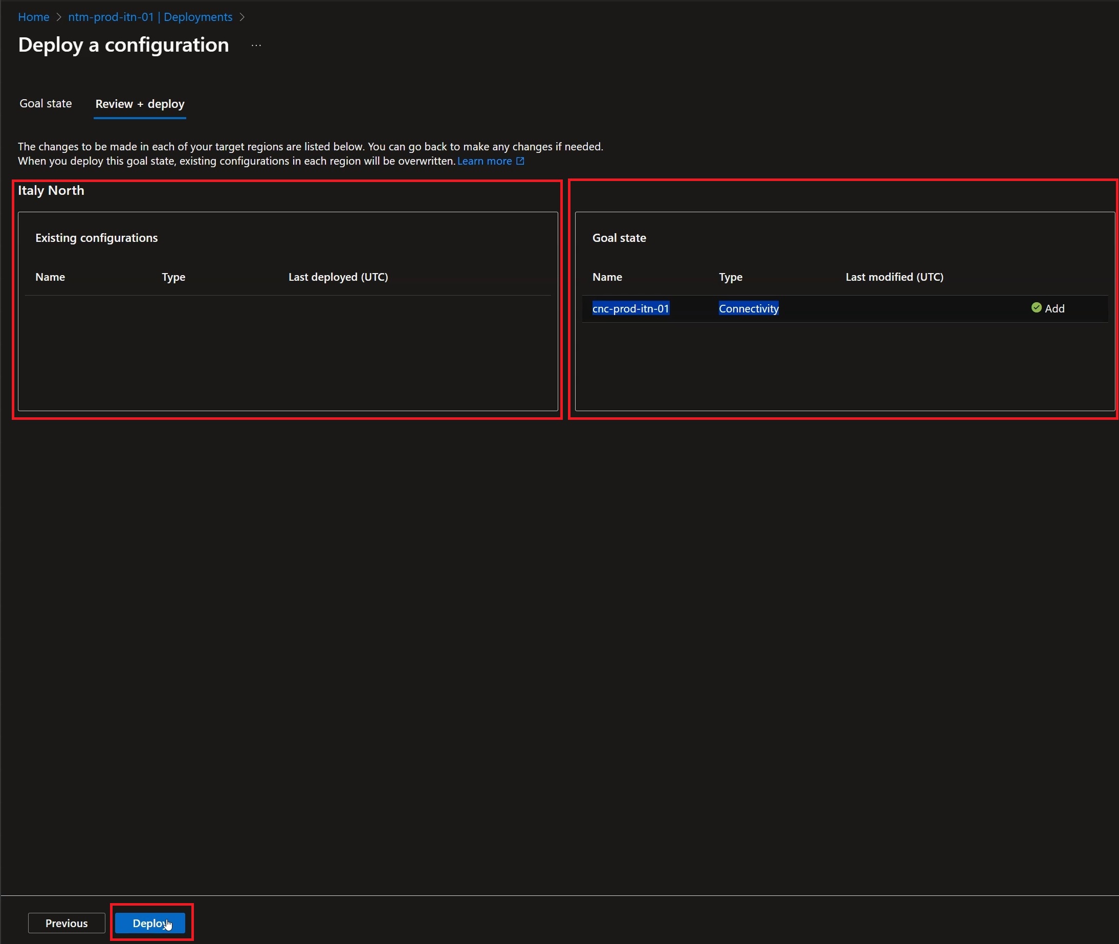
Figure 36: After reviewing the new configuration click “Deploy”
In the “Deployments” section of the Virtual Network Manager you can check the status of the deployment, which now reads “Succeeded”:
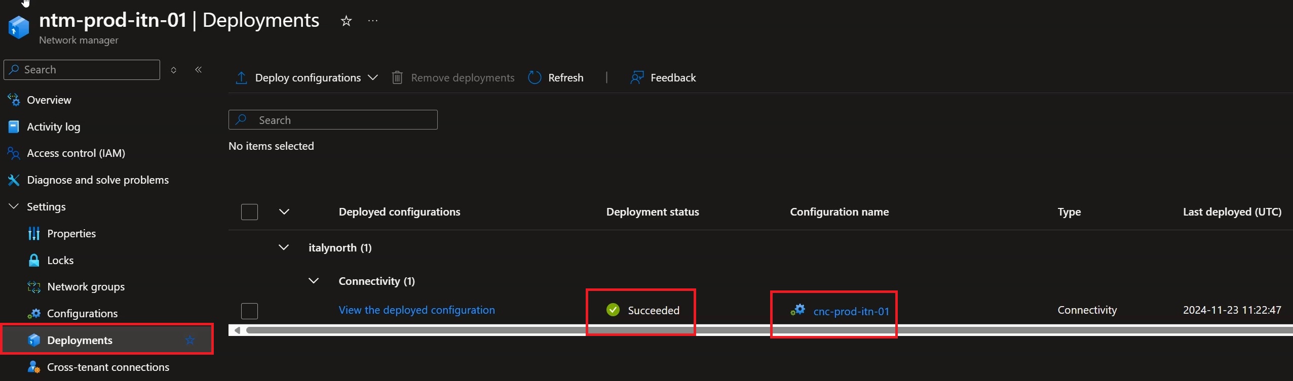
Figure 37: When the operation is complete, move to deployments and verify that the status is “Succeeded”
At this point, moving to the HUB network, you can verify that two Peerings have been created for the spokes that are part of the “Network Group”:
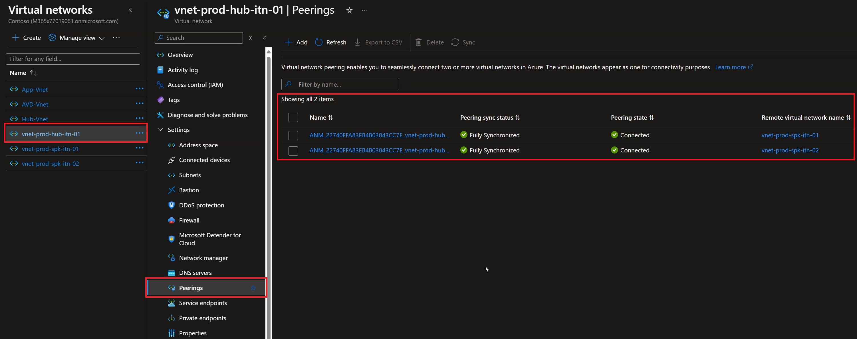
Figure 38: Moving to the Hub Virtual Network you can verify that the Peerings have been added by the VNet Manager
Conclusions
Azure Virtual Network Manager is an accelerator of our deployments within Microsoft Azure. It guarantees granular control over Virtual Networks — the true single pane of glass in networking management — allowing us not only to deploy network topologies, but also NSG configurations via Security Admin rules, or to act as an IPAM, which today is still in preview.
When should you use this tool? As always, the answer depends on your needs, but when the number of Subscriptions grows and the complexity of your networking increases, a tool like this really solves a lot of problems.
Here are some useful links to dig deeper into these topics:
https://learn.microsoft.com/en-us/azure/architecture/networking/architecture/hub-spoke
https://learn.microsoft.com/en-us/azure/virtual-network-manager/overview